Le sildénafil présent dans Kamagra exerce une inhibition réversible de la PDE5, modulant la cascade GMPc et favorisant une vasodilatation localisée. L’absorption digestive varie selon la forme utilisée, comprimés classiques ou gels oraux. La distribution tissulaire est large et la liaison protéique élevée, avoisinant 96 %. La métabolisation hépatique génère un métabolite actif contribuant à l’effet pharmacologique global. La demi-vie reste courte, avec disparition plasmatique en quelques heures. Les interactions significatives concernent surtout les nitrés organiques et inhibiteurs puissants du CYP3A4. Dans les publications techniques, kamagra en ligne est souvent cité dans le cadre d’analyses comparatives portant sur les différences de formulations et de cinétique d’absorption.
Microsoft word - clima 2010 - paper 1002.doc
Impact of boundary conditions on the development of the thermal plume above a sitting human body
Daria Zukowska1,*, Zbigniew Popiolek2 and Arsen Melikov1 1International Centre for Indoor Environment and Energy, (www.ie.dtu.dk), Department of Mechanical Engineering, Technical University of Denmark.
2Department of Heating, Ventilation and Dust Removal Technology, Silesian University of
*Corresponding email: dz@byg.dtu.dk SUMMARY The phenomenon of the thermal plume above a heat source has been reported in the literature as being influenced by a large number of factors. The objective of the present study is to identify the impact of the boundary conditions on the characteristics and development of the thermal plume above a sitting occupant. CFD predictions were performed to explain the reason for a skewness in the thermal plume above a sitting thermal manikin with realistic body shape, size, and surface temperature distribution, measured in a climate chamber with mean radiant temperature equal to the room air temperature, no radiant temperature asymmetry, and air velocity lower than 0.05 m/s. The results of the CFD predictions showed that even a small non-uniformity in the temperature field (±0.01ºC) or in the velocity field (±0.005 m/s) of the surrounding environment affects the development of the thermal plume above a sitting person and causes a skewness of the plume cross-section. INTRODUCTION
Occupants will become one of the major heat sources in rooms in the future and the thermal plumes generated by them will therefore determine the room air distribution and thus have an impact on the indoor environment. The phenomenon of the thermal plume above a heat source has been reported in the literature as being influenced by a large number of factors, e.g. thermal stratification, location of the heat source in a room, changes of conditions in the plume surroundings, unsteady flow in the convective boundary layer, etc. [1-3]. The initial flow generated by a heat source depends on the surface area, geometrical shape and surface temperature of the source. The present study is part of a study on factors affecting the development of the thermal plume above a sitting person [4,5] and on the influence of the occupant thermal plume on air distribution in a room [6]. The objective of the present study is to identify the impact of the boundary conditions on the characteristics and development of the thermal plume above a sitting occupant. In this study CFD simulations were used to predict the airflow above a sitting person and to explain a skewness of the plume generated by a thermal manikin in full- scale measurements. METHODS
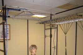
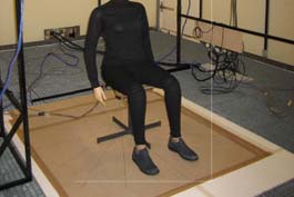
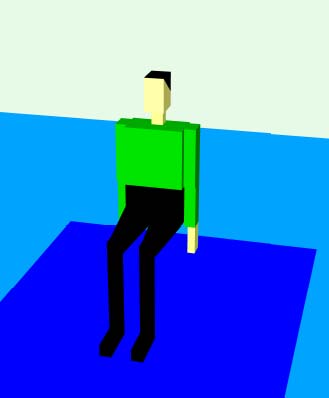
A full-scale experiment was conducted in a climate chamber with dimensions 4.7 x 6.0 x 2.5 m (W x L x H) ventilated with upward piston flow. The air was supplied through the whole floor area and exhausted through an opening of 1.8 x 1.8 m in the centre of the ceiling (however, leakage through the rest of the ceiling cannot be neglected due to the construction of the ceiling). The condition in the chamber during the investigation was: air temperature 23ºC, air velocity below 0.05 m/s, thermal stratification 0.07 K/m and no radiant temperature asymmetry. A 17-segment thermal manikin was used to simulate a sitting person. The manikin body is shaped to resemble accurately the body of an average Scandinavian woman 1.7 m in height. During the investigation the manikin was dressed in tight-fitting clothing and was seated on a light support (Figure 1). The top of the head of the sitting manikin was at a height of 1.23 m. The manikin was positioned in the centre of the room on a plate (1.6 x 2.0 m). Simultaneous measurements of the air speed and temperature across the plume cross-section 0.7 m above the head of the sitting thermal manikin were performed with 16 omnidirectional velocity sensors and 17 constantan-copper thermocouples attached to the horizontal arm of a traversing system as described in [4]. Results from the full-scale experiment showed that the thermal plume above the manikin was skewed approx. 30-45º to the left side of the chamber (Figure 2). Possible reasons for the plume skewness were investigated by CFD simulations. The CFD simulations were conducted by using the commercial program “Flovent”. A virtual manikin sitting in a room with size and environmental conditions as in the full-scale experiment was used. The virtual manikin (Figure 1) was built to simulate as close as possible the body size and shape as well as the heat loss from the thermal manikin. The convective heat loss from the whole body of the virtual manikin was 21 W, which corresponds to 24% of the total heat [4] supplied to the thermal manikin during the full-scale experiment. The air temperature at floor level and the temperature of the walls were simulated to be 23ºC, while the air velocity at floor level was assumed to be 0.030 m/s. Such values of air temperature and air velocity were treated as a uniform condition.
Figure 1. The female thermal manikin used in full-scale measurements and the virtual manikin used in CFD simulations.
Three numerical grids with different cell sizes were defined. The cell size of the uniform base grid in the entire modelled space was 0.08 x 0.08 x 0.08 m. Local grids were applied for the region of the manikin and the plume (size of the region: 0.58 x 0.92 x 1.96 m, size of cells: 0.02 x 0.02 x 0.04 m) and the wider region covering also the edges of the plume (size of the region: 1.04 x 1.44 x 2.45 m, size of cells: 0.04 x 0.04 x 0.04 m). The total grid size was 303,870. The k-ε turbulence model was applied. In order to explain the skewness of the thermal plume obtained in the full-scale measurements, the effect of the size and location of the exhaust was checked. Moreover, the impact of non-uniformity of the background air temperature and air velocity on the development of the thermal plume above the manikin was investigated. In total six different cases were studied by CFD simulations:
U1 – uniform environment – air supplied with the same temperature and velocity through the
whole area of the floor and exhausted uniformly through the whole ceiling area;
U2 – uniform environment – air supplied with the same temperature and velocity through the
whole area of the floor but 30% of the air exhausted through the central opening 1.8 x 1.8 m, and the remaining 70% uniformly through the rest of the ceiling;
T1 – non-uniform temperature environment – air supplied with the same velocity but air
temperature 0.01ºC lower on the right side of the manikin and 0.01ºC higher on the left side of the manikin than for the rest of the room at the floor level (23ºC). 30% of the air exhausted though the central opening, and the remaining 70% uniformly through the rest of the ceiling;
T2 – non-uniform temperature environment – air supplied with the same velocity but air
temperature 0.02ºC lower on the right side of the manikin and 0.02ºC higher on the left side of the manikin than for the rest of the room at the floor level (23ºC). 30% of the air exhausted though the central opening, and the remaining 70% uniformly through the rest of the ceiling;
V1 – non-uniform velocity environment – air supplied with the same temperature but velocity
0.005 m/s lower on the right side of the manikin and 0.005 m/s higher on the left side of the manikin than for the rest of the room at the floor level (0.030 m/s). 30% of the air exhausted through the central opening, and the remaining 70% uniformly through the rest of the ceiling;
V2 – non-uniform velocity environment – air supplied with the same temperature but velocity
0.010 m/s lower on the right side of the manikin and 0.010 m/s higher on the left side of the manikin than for the rest of the room at the floor level (0.030 m/s). 30% of the air exhausted through the central opening, and the remaining 70% uniformly through the rest of the ceiling.
RESULTS
The thermal plume above a sitting person appears to be very sensitive to the condition in the background. Contour maps of mean air velocity in the thermal plume 0.7 m above the head of a sitting manikin (1.93 m above the floor level) were used to compare results from full-scale measurements and CFD simulations. The beginning of the coordinate system (X=0, Y=0) used in the maps is located in the middle of the top of the manikin head which also corresponds to the middle of the ceiling. Figure 2 shows results from the physical measurements. It is evident that the plume cross-section was turned approximately 45º to the left side of the chamber. The plume is also more to the front of the manikin due to the impact of the flow from the legs and thighs.
Figure 2. Contour map of mean air velocity in the thermal plume 0.7 m above the head of a sitting thermal manikin. The CFD predictions showed that the location and size of the exhaust does not affect deformation of the plume. The maps in Figure 3 look very similar independent of whether air from the simulated room was exhausted uniformly through the whole area of the ceiling or in proportion 30% to 70% (central opening 1.8 x 1.8 m and the rest of the ceiling). In both cases the plume was very symmetrical and no skewness was observed.
Figure 3. Contour maps of mean air velocity of the thermal plume for uniform background condition: uniform exhaust through whole ceiling area (left) and exhaust in proportion of 30/70% (right). However, the CFD simulations showed that non-uniformity in the background temperature field even as small as ±0.01ºC and velocity field as small as 0.005 m/s affects the development of the thermal plume above a sitting person. Figure 4 shows that the thermal plume is especially sensitive to non-uniformity in the temperature field and was skewed approx. 30-45º when a non-uniformity of ±0.01ºC was introduced. A smaller skewness in the development of the thermal plume was identified when non-uniformity in the velocity field existed (Figure 5) – approx. 10º was obtained for a non-uniformity of ±0.005 m/s and approx. 15º for ±0.010 m/s.
Figure 4. Contour maps of mean air velocity of the thermal plume for non-uniform temperature fields of 23.0±0.01ºC (left) and 23.0±0.02ºC (right).
Figure 5. Contour maps of mean air velocity of the thermal plume for non-uniform velocity fields of 0.030±0.005 m/s (left) and 0.030±0.010 m/s (right). Non-uniformity of the environment on the right and left sides of the manikin causes a skewness of the plume. The plume turned in a direction of higher values of the background velocity or temperature. The central part of the plume with air velocities at the level of 0.24-0.30 m/s is more resistant to the disturbances, but the part of the plume above the manikin thighs is more influenced by the boundary condition, which cause that the plume skews. The CFD predictions gave in all cases much more concentrated plume cross-sections than the measurements. Table 1 presents the value of maximum velocity and its position for each of the described thermal plumes. It is seen that the maximum velocity in the measured plume is much lower than in the plumes simulated in CFD. It is also much more moved to the back of the manikin head in comparison with the CFD simulations. The full-scale measurements give lower values of velocities due to a more complex body shape of the thermal manikin and more porous surface of its clothing in comparison to the virtual manikin, which cause that the flow in the convective boundary layer changes from laminar into turbulent at a lower height.
Table 1. Maximum velocity and its position in the thermal plumes 0.7 m above the head of a manikin.
CONCLUSIONS
CFD simulations reveal that the thermal plume generated by a sitting occupant is very sensitive to non-uniformity of air temperature and velocity fields in the background environment. Local non-uniformities in the surroundings as low as ±0.01ºC for air temperature cause skewness of the plume cross-sections of approx. 30-45º to the side of the higher values of the parameter. The plume is less sensitive to non-uniformity of air velocity in the background – skewness of approx. 10º for non-uniformity ±0.005 m/s. CFD simulations showed that the two different ways of exhausting air from the room – uniformly through whole ceiling area or 30% through central opening and 70% uniformly through the rest of the ceiling – have negligible effect on the thermal plume 0.7 m above the manikin head. REFERENCES
1.
Popiolek, Z. 1981. Problems of testing and mathematical modelling of plumes above human body and other extensive heat sources, A4-Serien no. 54, Royal Institute of Technology, Stockholm.
Kofoed, P. 1991. Thermal plumes in ventilated rooms, Ph.D. Thesis, Department of Building Technology and Structural Engineering, Aalborg University, Denmark.
Mundt, E. 1995. Displacement ventilation systems – Convection flows and temperature gradients, Building and Environment 30 (1) 129-133.
Zukowska, D, Popiolek, Z and Melikov, A. 2007. Impact of personal factors and furniture arrangement on the thermal plume above a human body, Proceedings of the 10th International Conference on Air Distribution in Rooms – Roomvent 2007, Helsinki, Vol. 3, pp. 137-144.
Zukowska, D, Melikov, A. and Popiolek, Z. 2007. Thermal plume above a simulated sitting person with different complexity of body geometry, Proceedings of the 10th International Conference on Air Distribution in Rooms – Roomvent 2007, Helsinki, Vol. 3, pp. 191-198.
Zukowska, D, Melikov, A. and Popiolek, Z. 2008. Impact of Thermal Plumes Generated by Occupant Simulators with Different Complexity of Body Geometry on Airflow Pattern in Rooms, Proceedings of the 7th International Thermal Manikin and Modelling Meeting – 7I3M, Coimbra, Portugal, Paper 8.
Chairman & CEO, Aethlon Medical, Inc. 3030 Bunker Hill Street, Suite 4000, San Diego, California 92109, USA The intent of this paper is to analyze how current options for treating H5N1 Avian Fluinfection may influence the commercialization of the Aethlon HemopurifierTM, atherapeutic device targeted to modulate the immune response and capture circulatingH5N1 virus. In the face of an ac
 METHODS